Architectural Foundations and the Modern Enterprise Paradigm
Kubernetes (K8s) was introduced by Google in 2014, building on its internal Borg cluster management system. In 2015, Kubernetes was contributed to the Cloud Native Computing Foundation, establishing a vendor-neutral ecosystem that now supports global infrastructure at organizations such as Netflix, Spotify, and Shopify.
The platform addresses a core operational challenge: managing large numbers of containers across distributed environments introduces significant complexity when handled manually. Kubernetes replaces this with a declarative, self-healing model. Engineers define the desired system state using YAML manifests, and Kubernetes continuously reconciles the actual state to match it—automating scheduling, failure recovery, scaling, and application rollouts.
According to the CNCF’s 2025 Annual Survey, Kubernetes adoption continues to grow, with 82% of container users running it in production (up from 66% in 2023). Additionally, 66% of organizations deploying generative AI models rely on Kubernetes to manage inference workloads. The platform has also expanded to support heterogeneous environments: KubeVirt enables management of virtual machines alongside containers, while K3s provides a streamlined option for edge and resource-constrained deployments.
Understanding Kubernetes requires examining its two primary layers: the control plane (orchestration layer) and worker nodes (execution layer).
Control Plane Anatomy: The Orchestration Layer
A Kubernetes deployment is referred to as a cluster. The control plane maintains a global view of the cluster, makes scheduling decisions, and continuously drives the system toward its desired state.
Rather than being a single process, the control plane consists of multiple specialized components that operate together. These components are typically distributed across several nodes to ensure high availability and resilience.
Core Control Plane Components
Component | Role |
kube-apiserver | The primary entry point for all cluster operations. Handles authentication, RBAC authorization, schema validation, and admission control. Communicates over HTTPS and typically scales horizontally behind a load balancer. |
etcd | A distributed key-value store that persists all cluster data, including specifications, state, secrets, and policies. Uses the Raft consensus algorithm for consistency. Loss of etcd data without backup results in complete cluster state loss. |
kube-scheduler | Assigns unscheduled Pods to worker nodes using a two-phase process: filtering (eliminates unsuitable nodes) and scoring (ranks remaining nodes based on resource usage, affinity, and topology). |
kube-controller-manager | Runs multiple reconciliation loops that continuously compare desired and actual states and take corrective actions. |
cloud-controller-manager | Integrates the control plane with cloud provider APIs (e.g., AWS, Azure, GCP) to manage resources such as load balancers, networking, and storage. |
Controller Responsibilities
Within the controller manager, each controller is responsible for a specific domain:
Controller | Responsibility |
Node Controller | Detects node failures through missed heartbeats and reschedules affected Pods. |
ReplicaSet Controller | Maintains the desired number of Pod replicas and replaces failed instances. |
Endpoints Controller | Updates Service-to-Pod mappings as Pods are created or removed. |
Service Account Controller | Creates default service accounts and API credentials within new namespaces. |
Admission Control and Policy Evolution
Admission control serves as the final gate within the API server before changes are persisted. It follows a strict two-phase pipeline:
- Mutating controllers modify incoming requests
- Validating controllers enforce rules and accept or reject requests
As of Kubernetes v1.36, this pipeline includes CEL-based policy mechanisms that reduce reliance on external webhook infrastructure:
API | Status (v1.36) | Purpose |
ValidatingAdmissionPolicy | GA (since v1.30) | Enables in-process validation rules without requiring external webhook servers. |
MutatingAdmissionPolicy | GA (since v1.36) | Allows resource mutation directly within the API server using CEL, reducing latency and operational overhead. |
Both mechanisms operate entirely within the kube-apiserver, offering lower latency, eliminating TLS management overhead, and improving reliability compared to external admission webhooks.
API Extensibility: CRDs, Operators, and Admission Control
One of the most significant architectural strengths of Kubernetes is its extensible API. The platform is intentionally designed to allow users to define new resource types and embed domain-specific operational logic without modifying the core system.
Custom Resource Definitions (CRDs)
Custom Resource Definitions (CRDs) enable the creation of new resource types within the Kubernetes API. Once registered, these resources are treated as first-class objects, similar to built-in resources such as Pods or Services. Users can create and manage Custom Resources (CRs) using standard tools like kubectl and declarative YAML manifests.
The API server manages key aspects automatically, including storage, schema validation (via OpenAPI v3), role-based access control (RBAC), and versioning.
It is important to distinguish between:
- CRD: the schema or definition
- CR: an instance of that schema
This relationship is conceptually similar to a class and its object instance in programming.
Common examples include:
- Certificate and ClusterIssuer in cert-manager
- ServiceMonitor and PrometheusRule in the Prometheus Operator
- VirtualService and DestinationRule in Istio
The Operator Pattern
A CRD defines structure but does not perform any actions. The Operator pattern extends this by pairing a CRD with a custom controller. This controller monitors changes to Custom Resources and runs a reconciliation loop to ensure that the actual system state matches the declared desired state.
This approach enables teams to encode operational knowledge directly into Kubernetes.
Layer | Description | Example |
CRD | Schema registered with the API server | databases.example.com |
Custom Resource (CR) | Instance of the schema | A specific Database object |
Operator / Controller | Watches CRs and enforces desired state | Provisions and manages a PostgreSQL cluster |
Operators are commonly developed using frameworks such as Kubebuilder or the Operator SDK. At scale, they are often managed using Operator Lifecycle Manager (OLM), which supports installation, upgrades, and dependency management across clusters.
API Extensibility vs. Admission Control
CRDs extend what Kubernetes can manage, while admission control governs how API requests are processed.
As discussed earlier, ValidatingAdmissionPolicy and MutatingAdmissionPolicy are integral to this model. They allow organizations to enforce policies directly within the Kubernetes API, reducing reliance on external webhook-based systems and improving operational consistency.
Worker Node Mechanics: The Distributed Compute Engine
While the control plane is responsible for decision-making, worker nodes execute those decisions. Each worker node is a physical or virtual machine that runs application workloads in containers.
Every node includes three primary components that coordinate with the control plane to run Pods.
Core Node Components
Component | Role |
kubelet | The primary node agent. Monitors the API server for assigned Pods, translates specifications into runtime instructions via the Container Runtime Interface (CRI), and reports node and Pod health back to the control plane. |
kube-proxy | Implements the Kubernetes Service abstraction by maintaining network routing rules (iptables or IPVS) to direct traffic from a Service’s virtual IP to the appropriate Pods. |
Container Runtime | Executes containers. The kubelet interacts with it through the CRI, a standardized gRPC interface that decouples Kubernetes from specific runtime implementations. |
CRI-Compliant Runtimes
Runtime | Profile |
containerd | Industry standard; used by managed services such as AWS EKS, GKE, and AKS |
CRI-O | Designed specifically for Kubernetes; widely used in Red Hat and OpenShift environments |
gVisor / Kata Containers | Sandboxed runtimes that provide enhanced isolation for multi-tenant or security-sensitive workloads |
Docker Engine is no longer supported as a Kubernetes runtime. Modern deployments use containerd (which Docker itself relies on internally). From Kubernetes v1.26 onward, runtimes must support the v1 CRI API; otherwise, the kubelet will not register the node.
The Pod Abstraction and Granular Lifecycle Management
The Pod is the smallest deployable unit in Kubernetes. It represents a logical grouping of one or more containers that:
- Are scheduled onto the same node
- Share a network namespace (single IP address)
- Can share storage volumes
In most production scenarios, a Pod contains a single primary application container.
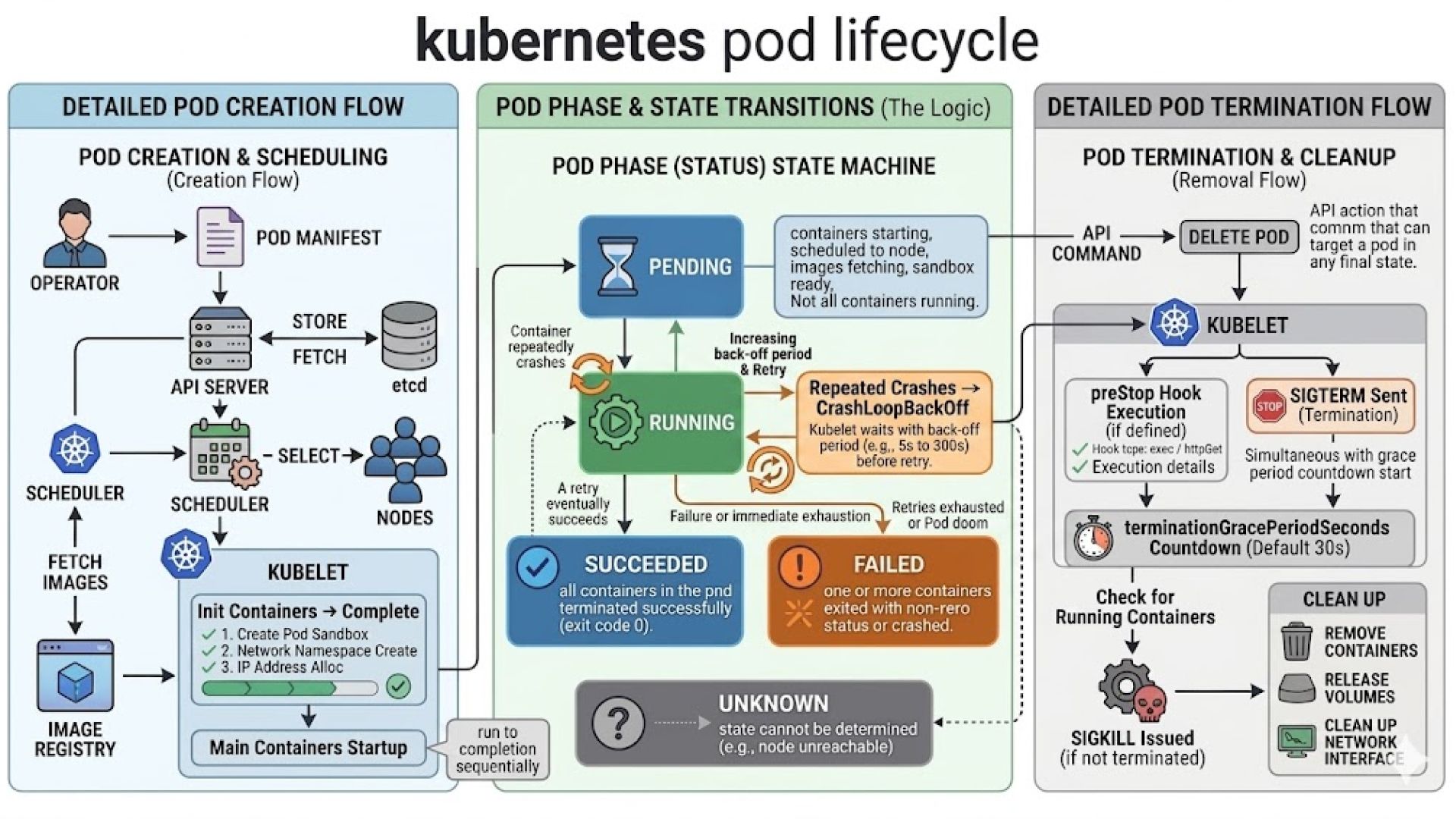
Pod Lifecycle Phases
Phase | Meaning |
Pending | Accepted by the cluster but awaiting scheduling or image download |
Running | Assigned to a node; at least one container is active |
Succeeded | All containers completed successfully and will not restart |
Failed | At least one container exited with an error |
Unknown | Node communication failure prevents status determination |
Startup Sequence and Health Probes
Before application containers start, init containers execute sequentially to perform setup tasks such as configuration initialization or dependency checks.
Once initialization is complete, the kubelet activates three types of health probes:
Probe | Failure Action |
startupProbe | Delays liveness and readiness checks until the application is fully initialized |
livenessProbe | Restarts the container if it becomes unresponsive or enters a failed state |
readinessProbe | Removes the Pod from Service load balancing when it cannot safely handle traffic |
Quality of Service (QoS) Classes
Each Pod is assigned a QoS class at creation time based on its resource configuration. This classification determines eviction priority under resource pressure and does not change during the Pod’s lifetime.
QoS Class | Condition | Eviction Priority |
Guaranteed | Requests equal limits for all containers | Lowest (last evicted) |
Burstable | Requests defined, but not equal to limits | Medium |
BestEffort | No resource requests or limits defined | Highest (first evicted) |
Graceful Termination
When a Pod is deleted, Kubernetes initiates a controlled shutdown process. It sends a SIGTERM signal to all containers and removes the Pod from Service endpoints to prevent new traffic. This allows in-flight requests to complete.
After the configured terminationGracePeriodSeconds (default: 30 seconds), any remaining processes receive a SIGKILL signal.
Controller Behavior and Operational Considerations
Deployment is the default choice for stateless workloads. It manages a ReplicaSet that enforces the desired number of replicas and orchestrates updates using rolling strategies. Parameters such as maxUnavailable and maxSurge allow teams to balance availability and rollout speed, making Deployments suitable for continuous delivery pipelines.
StatefulSet introduces guarantees that Deployments intentionally avoid. Pods are created, updated, and deleted in a defined order, and each Pod is assigned a stable network identity and persistent storage. These guarantees are essential for distributed systems such as databases, where instance identity and data locality directly affect correctness and performance.
DaemonSet operates at the infrastructure level. It ensures that a specific Pod runs on every node (or a subset defined by node selectors). This makes it the standard approach for deploying system-level services such as logging agents, monitoring collectors, networking components, and security tools.
Job and CronJob are designed for workloads with a defined lifecycle. A Job runs until a specified number of successful completions is reached, while a CronJob schedules Jobs at regular intervals. These abstractions are commonly used for data processing, backups, and maintenance tasks.
Selecting the appropriate controller is not simply a matter of preference—it directly impacts application availability, data integrity, rollout behavior, and recovery strategies.
Advanced Cluster Networking and the Gateway API Transition
Kubernetes networking is based on a foundational principle: every Pod receives a unique IP address, and all Pods can communicate with each other directly without network address translation (NAT). This flat network model simplifies service discovery and communication but requires a robust implementation layer.
This implementation is provided by a Container Network Interface (CNI) plugin. Kubernetes defines the networking model, but the CNI plugin enforces it in practice.
Common CNI solutions include Cilium, Calico, Flannel, and Weave. These differ in capabilities such as:
- Support for eBPF-based packet processing
- Native enforcement of NetworkPolicy
- Encryption of pod-to-pod traffic
- Observability and traffic visibility
As a result, selecting a CNI plugin is a significant architectural decision that influences security, performance, and operational visibility.
Services and Traffic Routing
Because Pods are short-lived and their IP addresses change frequently, Kubernetes introduces the Service abstraction to provide stable endpoints. A Service exposes a consistent virtual IP and routes traffic to a dynamic set of Pods selected via labels.
Service Type | Behaviour |
ClusterIP | Exposes the Service internally within the cluster |
NodePort | Opens a port on each node and forwards traffic to the Service |
LoadBalancer | Provisions an external load balancer via the cloud provider |
ExternalName | Maps the Service to an external DNS name |
This abstraction decouples service consumers from the lifecycle of individual Pods, enabling seamless scaling and updates.
Gateway API and the Evolution Beyond Ingress
The traditional Ingress model centralized routing configuration in a single resource, often extended through controller-specific annotations. While functional, this approach introduced inconsistencies and limited extensibility.
The Gateway API represents a structured evolution of this model. It introduces role-based resource separation, aligning responsibilities across infrastructure, platform, and application teams.
Resource | Owner | Purpose |
GatewayClass | Infrastructure administrator | Defines which controller implementation manages Gateways |
Gateway | Cluster operator | Configures entry points, protocols, ports, and TLS settings |
HTTPRoute | Application developer | Defines routing rules and maps requests to backend Services |
This separation improves governance and aligns naturally with Kubernetes RBAC, enabling teams to operate independently while maintaining clear boundaries.
Compared to Ingress, the Gateway API provides:
- Stronger extensibility through a structured resource model
- Reduced reliance on annotations and controller-specific behavior
- Improved portability across implementations
Migration tooling such as ingress2gateway supports transition by converting existing configurations into Gateway API resources.
Persistent Storage, State Management, and Dynamic Provisioning
Containers are stateless by default. Any data written to a container’s local filesystem is lost when the container restarts or is rescheduled. For stateful workloads, Kubernetes provides a storage abstraction that separates application requirements from underlying infrastructure.
Storage Object Model
Kubernetes storage is built on three core abstractions:
Object | Role |
PersistentVolume (PV) | Represents a provisioned storage resource independent of Pod lifecycle |
PersistentVolumeClaim (PVC) | Defines a request for storage with specific requirements (size, access mode, class) |
StorageClass | Specifies how storage is dynamically provisioned, including the CSI driver and configuration parameters |
This model allows developers to request storage declaratively, without needing to manage infrastructure details directly.
Static vs. Dynamic Provisioning
Static provisioning requires administrators to manually create PersistentVolumes in advance. While this offers precise control, it does not scale efficiently in dynamic environments.
Dynamic provisioning addresses this limitation. When a PVC references a StorageClass, Kubernetes automatically provisions storage using the associated CSI driver, creates the corresponding PV, and binds it to the claim. This process eliminates manual intervention and supports scalable, on-demand storage allocation.
Container Storage Interface (CSI)
The Container Storage Interface (CSI) standardizes how Kubernetes interacts with external storage systems. Storage providers implement CSI drivers to integrate their platforms with Kubernetes.
This approach offers several advantages:
- Decouples storage innovation from Kubernetes release cycles
- Enables independent updates and feature delivery
- Provides consistent lifecycle management across storage backends
CSI has replaced legacy in-tree volume plugins, making it the standard mechanism for storage integration.
Volume Access Modes and Reclaim Policies
Access modes define how volumes can be mounted:
Access Mode | Behaviour |
ReadWriteOnce (RWO) | Mounted read-write by a single node |
ReadOnlyMany (ROX) | Mounted read-only by multiple nodes |
ReadWriteMany (RWX) | Mounted read-write by multiple nodes |
ReadWriteOncePod (RWOP) | Mounted read-write by a single Pod |
Reclaim policies define what happens to storage after a PVC is deleted:
- Delete: Automatically removes the underlying storage
- Retain: Preserves the storage for manual recovery or auditing
Volume Snapshots
Kubernetes supports point-in-time backups through the VolumeSnapshot API. These snapshots enable data recovery, cloning, and migration workflows.
Recent enhancements include support for group snapshots, which allow multiple volumes to be captured in a consistent state. This is particularly important for distributed applications that store related data across multiple volumes, ensuring data integrity during backup and restore operations.
Zero-Trust Security, Cluster Hardening, and Supply Chain Defense
Kubernetes is designed for ease of adoption by default, not for secure-by-default operation. A newly provisioned cluster allows containers to run as root, permits unrestricted network communication between workloads, and automatically mounts API credentials into Pods. Production readiness requires systematically replacing these permissive defaults with explicit, enforceable controls across all layers.
A practical approach to cluster hardening can be understood through four primary enforcement layers:
The Four Enforcement Layers
Layer | Mechanism | What It Controls |
Identity & Access | RBAC + OIDC | Who can perform which API operations on which resources |
Workload Isolation | Pod Security Standards (PSS) | What containers are allowed to do at runtime |
Network | NetworkPolicy | Which workloads can communicate and over which ports |
Supply Chain | Image signing + admission control | Whether a container image is trusted before execution |
Identity and Access Control
Role-Based Access Control (RBAC) governs authorization within the Kubernetes API. The guiding principle is least privilege: each workload should use a dedicated ServiceAccount with only the permissions required for its function.
Cluster-wide administrative roles should be tightly restricted and never used as defaults for applications or users. Integrating external identity providers via OIDC further strengthens security by replacing static credentials with short-lived, automatically rotating tokens, improving traceability and reducing credential exposure risk.
Workload Isolation with Pod Security Standards
Pod Security Standards (PSS), introduced as the successor to PodSecurityPolicy, define baseline security expectations for workloads at the namespace level. Three profiles are available:
- Privileged — unrestricted; intended for trusted system components
- Baseline — prevents known privilege escalation paths while maintaining compatibility
- Restricted — enforces modern security best practices (non-root execution, restricted capabilities, read-only filesystems)
For most production environments, the Restricted profile should be the default, with exceptions granted only where operationally necessary.
Network Segmentation
By default, Kubernetes clusters have no network segmentation—any Pod can communicate with any other Pod. This flat model increases risk if a workload is compromised.
NetworkPolicy introduces fine-grained control by defining allowed communication paths. A common best practice is to implement a default-deny policy at the namespace level, then explicitly allow only required traffic flows. This approach significantly reduces lateral movement within the cluster and strengthens overall isolation.
Supply Chain Security
Supply chain security focuses on controlling what enters the cluster before execution. This includes:
- Scanning container images for vulnerabilities during CI pipelines
- Cryptographically signing images to verify integrity and origin
- Enforcing policies at admission time
Admission controls—such as ValidatingAdmissionPolicy or policy engines like OPA Gatekeeper—can ensure that only trusted, compliant images from approved registries are deployed.
Together, these controls establish a zero-trust posture, where every workload is verified before execution rather than assumed to be safe.
Multi-Cluster Architecture and Fleet Governance
Operating a single Kubernetes cluster is relatively well understood. The greater challenge lies in managing multiple clusters across regions, cloud providers, and environments. As of 2026, multi-cluster architectures have become standard for organizations operating at scale, particularly those with global workloads, regulatory requirements, or hybrid infrastructure strategies.
Why Multiple Clusters
A single cluster represents a shared failure domain. Issues such as control plane outages, configuration errors, or resource exhaustion can impact all workloads simultaneously.
Multiple clusters introduce clear isolation boundaries based on:
- Geography (regional deployments)
- Environment (development, staging, production)
- Compliance requirements
- Workload sensitivity
This segmentation reduces blast radius and improves resilience, availability, and governance.
Fleet Governance Challenges
As the number of clusters increases, operational complexity grows non-linearly. Key challenges include:
Challenge | Consequence if Unaddressed |
Configuration drift | Clusters diverge from intended state, creating inconsistencies |
Fragmented RBAC | Inconsistent access control across clusters increases risk |
Upgrade coordination | Version misalignment introduces compatibility and security issues |
Cost visibility | Lack of centralized tracking complicates cost management and allocation |
GitOps as the Governance Foundation
GitOps has emerged as the standard model for managing multi-cluster environments. In this approach, Git repositories act as the single source of truth for all cluster configurations.
Tools such as Argo CD and Flux continuously synchronize declared configurations to clusters. Any deviation from the desired state is automatically detected and reconciled.
This model provides:
- Full auditability of changes
- Consistent configuration across environments
- Improved reproducibility and rollback capabilities
Workload Placement and Cluster Lifecycle Management
For distributing workloads across clusters, platforms such as Karmada and Open Cluster Management enable policy-driven scheduling and centralized governance using Kubernetes-native APIs.
Cluster lifecycle management is increasingly handled through Cluster API, which applies the same declarative and reconciliation-based model used for applications to the clusters themselves. This enables consistent provisioning, upgrades, and decommissioning across environments.